INSPECTION PROBLEMS AND SOLUTIONS DURING EQUIPMENT FABRICATION, i.e., PRESSURE VESSELS
Do you know what is the better way to avoid problems during the fabrication of Pressure Vessels?
In this article I will provide you information about the problems we can face and their solutions, during the inspection of pressure vessels when manufacturing. I’m sure it will help you to understand the process easier and find out what the crucial points are when inspecting.
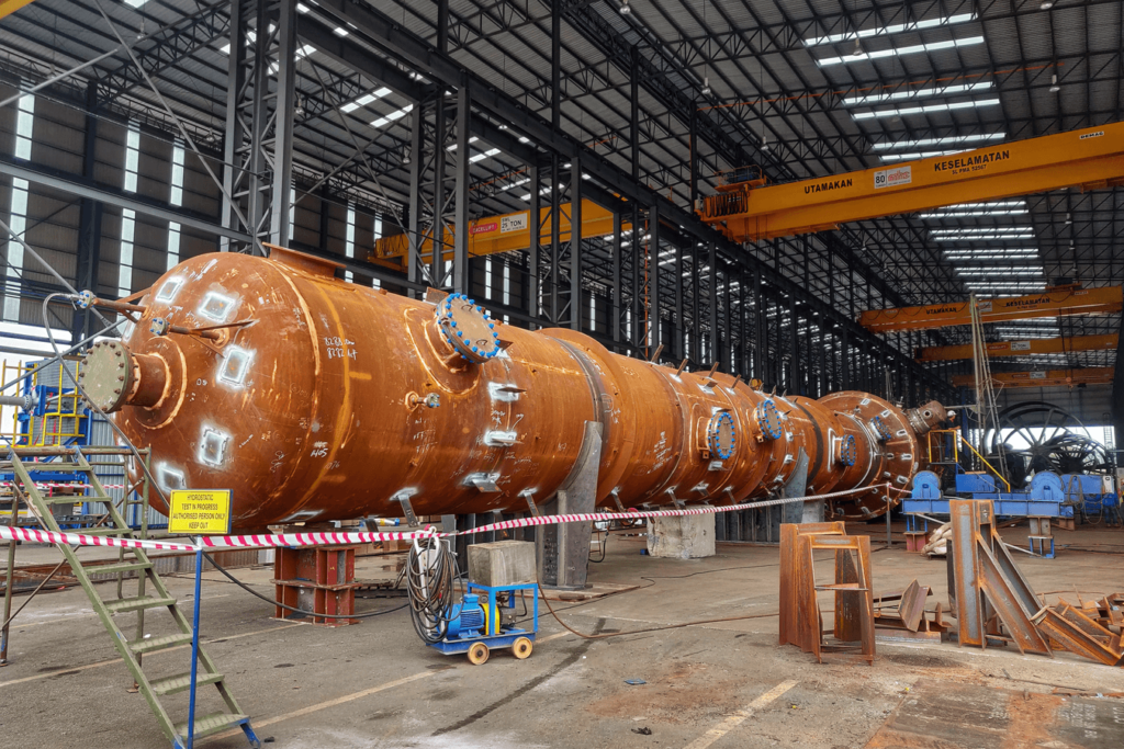
The fabrication of a pressure vessel must be an accurate process. Immense care needs to be taken on each fabrication step in order to ensure that the quality of the vessel is excellent, and that the fabrication meets all the requirements.
Pressure Vessel
Pressure vessels are used in most processes in a refinery or petrochemical plant. They are used to contain process fluids. A pressure vessel can be used as a thermal reactor or a catalytic reactor to contain the chemical change required by the process; as a fractionator to separate various constituents produced in the reaction; as a separator to separate gases, chemicals, or catalyst from a product; as a surge drum for liquids; as a chemical treating unit; as a settling drum to permit separation of a chemical from a treated product; as a regenerator to restore a catalyst or chemical to its original properties; or as a heat exchanger, condenser, cooler, or other type of vessel for any of various other purposes.
Inspection
On the basis of ASME code section VIII division 1 or 2 and the relevant specifications, Inspection Test Plan (ITP) of pressure vessel fabrication is issued.
The inspection scope is mentioned in ITP. Certain contractors and clients have a preference to have strict controls and indicate them in the ITP as “hold point” or “witness point” in order check, witness and verify if the relevant activity has been performed with satisfactory results. While others have a preference to have more “Monitoring” or “Review” points for more review work.
This all rely on the equipment criticality. If the criticality is high then the assigned budget for the inspection by the client will be also high, and so if the budget is high then the inspection results will be more reliable.
Material Inspection
The first and foremost step of inspection begins from the technical inspection of the raw materials that in future utilized for the fabrication and assembling of pressure vessels. Based on ASME section II, standards and code, the generation of inspection report of material is compulsory. For other surplus materials, marking inspection will be considered satisfactory. In addition, the material test report or mill test report (MTR) must be provided by the manufacturer, if it is instructed on the purchase order. Normally, the certificates issued from mill for the components are already available at the manufacturer domain. The inspector checks if these certificates are according with the specifications of the purchased material. The review comprises of the following checks:
- Originality of the certificates
- Chemical compositions of the raw materials
- Mechanical properties including yield strength and the tensile strength of the materials.
- Heat treatment results of material
- NDT results.
Also Visual & Dimensional check and Positive Material Identification (PMI) will be performed, if required, in order to verify the correct dimensions and the compliance of the chemical composition of the required materials to be used.
When the raw material’s inspection is being finalized, a report is generated which address if the material is acceptable or not.
The processes of cutting, forming, edge preparation and joint fit-up are foundational to the quality of fabrication. Any inadequacies will greatly increase the risk of defects during further processing, for example:
- Plates that are not cut square can affect the straightness of cylindrical shells.
- Cut edges that are not properly cleaned can cause weld defects.
- Unresolved edge defects such as laminations in plates can cause weld defects.
- Improper curvature at the longitudinal edge of plates after bending may result in deviations from the permissible out-of-roundness.
Inspection during Welding Phase
Before starting any weld activity it is necessary to verify the weld bevels and the fit-up activities in order to check if they are satisfactory according to the relevant Welding Procedure Specification (WPS) and the proper Drawing.
Excessive gaps left by fit-up of joints for welding might initiate weld defects. Weld bevels must be cleaned and free from surface defects.
Welding material may be managed following the storage (temperature and humidity) and handling recommendations of welding consumable manufacturer. It is very important to verify that consumables have been stored and baked appropriately.
The welding activities of pressure vessel are being carried out according to an approved WPS supported by different Procedure Qualification Record (PQR) according to ASME Boiler and Pressure Code (BPVC) section IX. All welders and Welding operators involved in the fabrication must be qualified by a proper WPQR.
Preheating and interpass temperatures may be maintained as well as electrical parameters must be within the limits, as required in the proper WPS.
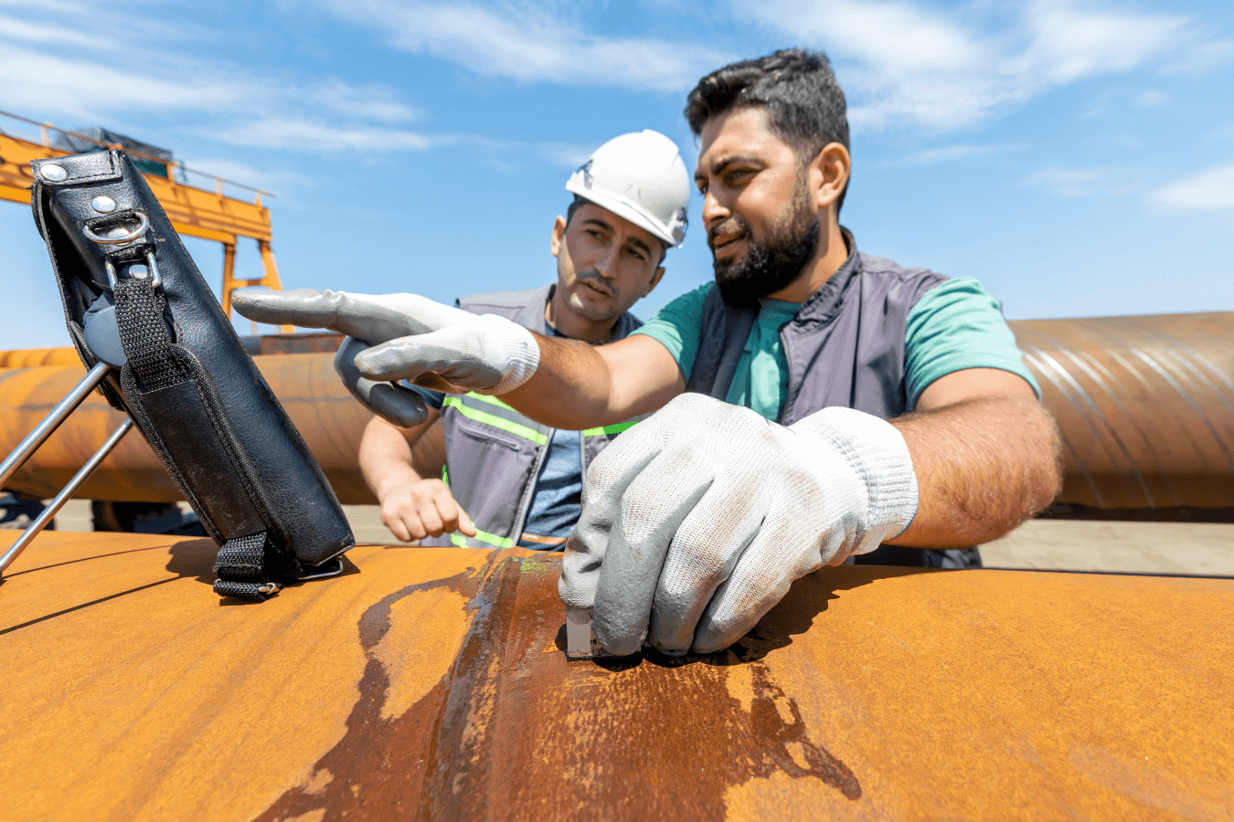
The inspection of the weldments will be carried out by visual inspection (VT) followed by magnetic particle examination (MT) and penetrant test (PT) and most of the time radiographic testing (RT) and ultrasonic testing (UT) are also implemented. In addition, for further confirmation of the weldments quality, Phased Array (P.A.) and Time-of-Flight Diffraction ultrasonic (TOFD) examination can be also perform.
In case any defect is found, weld repair has to be carried out.
The defective welds shall be removed by grinding, machining, or thermal gouging process. The groove shall be re-welded, by qualified welders, according to the qualified WPS. Before re-welding, the repairing area shall be re-examined by the Non-destructive Testing (NDT) required by the Code and relevant specifications, to verify the full removal of all defect. Such repair shall be recorded on Data Report.
Inspection of NDT
Non-destructive Testing (NDT) is defined as those inspection methods, which allow materials to be examined without changing the material itself and its usefulness. NDT is an integral part of the quality assurance program. A wide variety of NDT techniques are used to ensure the weld meets design specifications and does not contain defects.
Each NDT method has their own capability and adequate sensitivity to detect different discontinuities in the weld joints requiring examination for accept/reject evaluation.
The most commonly NDT methods used during weld inspection are shown in the following table:
| Type of Test | Symbols |
| Visual | VT |
| Magnetic Particle | MT |
| Wet Fluorescent Magnetic Particle | WFMT |
| Liquid Penetrant | PT |
| Leak | LT |
| Eddy Current | ET |
| Radiographic | RT |
| Ultrasonic | UT |
And the table below lists the common types and location of discontinuities.
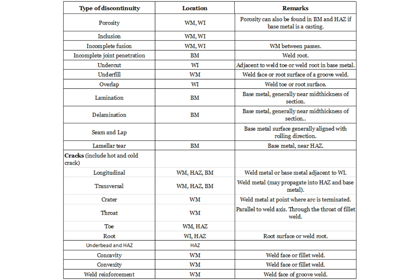
BM – Base Metal; WM – Weld Metal; HAZ – Heat Affected Zone; WI – Weld Interface
The inspector may have an adequate knowledge of NDT techniques and common discontinuities that can occur due to the specific base metals and weld processes, in order to assure that these discontinuities can be detectable with the technique employed.
NDT must be performed by qualified personnel.
Discontinuities and its Types
Porosity
These are the different types of porosity that can occur during fabrication:
– Scattered porosity
In scattered porosity the pores are uniformly distributed overall the weld surface. The cause is faulty welding techniques. The joint preparation procedure or materials may also result in the occurrence of scattered porosity. In case of slow solidification of weld metal, most of the gas evolves from the surface prior to the weld solidification. In such scenario, few pores will be generating in the weld.
To prevent this type of porosity, the weld should be slowly cooled by allow most of the gas to pass to the surface before solidification.
– Cluster porosity
Cluster porosity is defined as the localized group of pores having a haphazard geometric distribution. The main cause of cluster porosity is the initiation or termination of a weld pass.
– Piping porosity
Piping porosity, also called “wormhole porosity”, is a type of porosity having a length greater than its width and it position almost at right angle to the weld surface. In fillet welds piping porosity ranges from weld root to the weld surface. Piping porosity is generally found in welds that does not extends all the way to the surface and by vigilant excavation it can be revealed in welds metal subsurface.
– Aligned porosity
Aligned porosity, also known as “Linear Porosity”, is a localized array of pores in a linear direction. The shapes of the pores can be either spherical or elongated. The cause of aligned porosity is contamination that leads to the release of gas along the weld interface, interface of the weld beads, and near the weld root.
– Elongated porosity
Elongated Porosity is a form of porosity having a length greater than its width that lies approximately parallel to the weld axis.
Basically, to prevent all these kinds of porosity, it should be necessary a very good preheating of the weld bevel, it would be useful to use an electrode with a higher number of deoxidizers, and also is very important to restart the next pass above the end of the previous pass.
Inclusions
Inclusions are the entrapped foreign particles.
– Slag inclusions
These are recognized as discontinuities ensuing from the entrapment non-metallic products within the weld metal. During the welding or brazing process, slag inclusion is formed by the inclusion of both flux and the non-metallic impurities. They mostly appear in welds made with arc welding process that use flux as a shielding medium. However, the slag inclusion results due to inefficient welding techniques, lack of passable access for the welding joint and inappropriate cleaning of the weld between passes.
To prevent the formation of such inclusions, it will be needed to increase the welding intensity or perform a pre-heating of the weld joint, as well as grinding the narrow areas in order to gain access to the bottom of the joint.If a repair is needed, the weld should first be removed by grinding and then weld again.
– Tungsten inclusions
They are tungsten particles trapped in the welding metal and are unique to the metal GTAW process. In this process, a non-consumable Tungsten electrode is used for create the arc between the piece and the electrode. If the electrode is immersed in the metal, or if the current is set to a very high value, tungsten droplets will be deposited, or the tip the electrode and it will get stuck in the welding.
In order to prevent the formation of such inclusions, it is necessary to pay close attention during the welding activities, checking that the intensity used is correct and the process is performed with careful technique.If a repair is needed, the weld should first be removed by grinding and then re-weld again.
Incomplete Fusion
This is a weld discontinuity in which fusion does not happen between weld metal and fusion faces or adjoining weld beads because of inappropriate welding technique, unsuitable base metal preparation, or inappropriate joint designs. Deficits instigating partial fusion comprise deficient welding heat or lack of access to all fusion faces, or both. Except the weld joint is appropriately cleaned, the integrating adhering oxides interferes with complete fusion, even when there is appropriate entree for welding and proper welding heats are used.
To prevent the formation of such discontinuities, the welding must be perform with much attention with a not too pronounced electrode angle, checking that the intensity used isn’t too low, welding with a low travel speed, cleaning the base material and preheating of the joint bevel properly.If a repair is needed, first of all the defective area should be removed completely, this is sometimes difficult to find. Once removed, it should be re-welded.
Incomplete Joint Penetration
In this phenomenon the weld metal does not outspread through the joint thickness. The unpenetrated and un-fused area is an interruption explained as imperfect joint penetration. It may produce due to inadequate welding heat, indecorous joint design, or improper lateral control of the welding arc.
To prevent it, the welding process must be controlled using a not too low intensity, doing a very good pre-heating of the piece to be welded, an adequate root gap and an arc length not too short.If a repair is needed, it would be necessary to perform a backgouging and weld again.
Undercut
Undercut is a groove melted into the base metal adjacent to the weld toe or weld root and left unfilled by the weld metal. This groove generates a mechanical notch which is a stress concentrator. When undercut is measured inside the limits of specifications it is not considered a weld defect. Undercut is normally related with either improper welding techniques or excessive welding currents, or both.
To prevent undercuts it is necessary to adjust the welding machine parameters and carry out a very good cleaning of the metal to be welded before starting any weld activity.If a repair is needed, it will be carried out with a smaller electrode; often a low hydrogen electrode, with pre-heating.The area to be welded should generally be rectified before any action is taken.
Underfill
In underfill the weld face or root surface of a groove weld outspreads underneath the adjacent surface of base metal. It results from the failure of the welder to completely fill the weld joint.
In order to prevent its formation, the appropriate parameters and techniques must be applied according to the relevant weld, whether the intensity used during the process, such as the travel speed welding.If a repair is needed, it would be necessary to do another weld bead onto the last one in order to fill this lack of material; a previous preparation of the area by grinding is required.
Laminations
It is a type of base metal discontinuity with parting or weakness usually allied analogous to the worked surface of a rolled product. Laminations may be entirely inside and are frequently identified by non-destructive examination technique, i.e., by UT. They may also spread to an edge or end, where they are noticeable at the surface, and may be identified by VT, PT or MT methods. They may be discovered when cutting or machining exposes internal laminations.
Normally the rules establish that welds, on edges of plates where there is outcrop of laminations, are not allowed because these could create cracks that will propagate through the weld.
This table also lists the identification capabilities of various NDT methods for wide variety of discontinuities in the welding.
| Discontinuities | Inspection Methods | ||||||
| RT | UT | PTa,c | MTb,c,d | VTa | ET | LTe | |
| Porosity | A | O | A | O | A | O | A |
| Slag inclusion | A | O | A | O | A | ||
| Incomplete fusion | O | A | U | O | O | O | O |
| Incomplete joint penetration | A | A | U | O | O | O | U |
| Undercut | A | O | A | O | A | O | U |
| Overlap | U | O | A | A | O | O | U |
| Cracks | O | A | A | A | A | A | A |
| Laminations | U | A | A | A | A | U | U |
A – Applicable Method
O – Marginal applicability (depending on other factors such material thickness, discontinuity size, orientation and location)
U – Usually not used
a – surface; b – surface and slightly subsurface; c – weld preparation or edge of weld metal;
d – applicable only to ferromagnetic materials; e – applicable only to enclosed structure which may be sealed and pressurized during testing.
Radiographic Testing (RT)
RT is a volumetric examination procedure adept to examine the complete sample rather just surface and sub-surface examination. This test is employed to determine the surface and subsurface breaks after completed the weld specimen. The RT method uses the difference in absorption of radiation by solid metals in areas of incoherence. The transmitted radiations counter with the film, a hidden image was depicted, and when the film is created a perpetual image is formed of the weld.
This radiography technique is not restricted by the type of material or grain morphology. Surface and subsurface discontinuities can be detected by this technique.
Ultrasonic Testing (UT)
UT is performed to detect surface and subsurface cracks or defects. Ultrasonic sound waves of certain frequency for 00 probe and 700 are employed. An UT beam can only be transmitted through the metal, it will be completely reflected from the far-off surface of the material, metal/air interface. In addition, UT beam can partly or utterly reflect from the internal surfaces mainly, fissures, laminations, pores, and inclusion of non-metallic particles.
This method has the ability to identify most of the weld discontinuity such as cracks, slag, and incomplete fusion. However, it can also be used to verify base metal thickness and identify the defect size and shape precisely.
Magnetic Testing (MT)
In ferromagnetic materials, surface or near surface discontinuities can be detected by employing Magnetic Particle Examination (MT) technique. It is generally employed for the evaluation of weld joint surface, checking in-between steps of weld and back gouged surface. It is also employed for weldments that have discontinuities on or near the surface.
This process generates a low magnitude magnetic field in the material. When ferromagnetic particles are placed into the magnetic field these are attracted to the magnetic field that results due to discontinuities.
Penetrant Testing (PT)
PT is capable of detecting surface discontinuities in alloys ferrous and non-ferrous. Penetrating liquids can be used to inspect surfaces of welded joint, individual intermediate pass welding seams and completed welds. PT is commonly used in austenitic stainless steels where magnetic particle inspection is not possible. The inspector must recognize that many specifications limit contaminants in penetrating materials as they could affect negatively the welding or the materials. Most penetrant manufacturers provide certificates of materials showing the percentage of contaminants in their products, such as chlorine, sulfur and halogens. During the inspection by PT, the surface to be inspected must be completely clean and covered with a penetrant liquid that searches for and delves into the discontinuities connected with the surface. After the excess of penetrant from the surface is removed, one solvent powder suspension (developer) is applied by spraying. The liquid of any discontinuity bleeds out the surface and stains the coating dust. One depth indication is possible if the inspector observes and compares the size of the stain with the size of the opening visible on the surface. The larger the stain is in relation to the size of the visible opening on the surface, the greater the volume of the discontinuity.
Post Weld Heat Treatment
Heat treatment involves heating pressure vessel components or whole pressure vessels to high temperatures, holding the required temperature for a minimum time period, followed by cooling, all under control conditions. The typical purpose for post weld heat treatment is to relieve and distribute the residual stresses caused by forming and welding. These stresses will be at or near the yield strength. Heating the completed fabrication to around 600 ºC reduces the yield strength. There many benefits, these are the following: – Residual stresses in components such as flanges and tubesheets can cause distortion and warping. This can be made worse if material is removed from the component by machining after welding. Optimum dimensional stability is achieved by doing final machining after stress relieving. – The potential for stress corrosion cracking is reduced due to the steel having decreased hardness and higher ductility after stress relieving. – The potential for hydrogen induced cracking is minimized by allowing hydrogen to diffuse away from the welded area during heat treatment. – The resistance to brittle fracture can be improved; the same happens for other mechanical and metallurgical properties. It is very important to take note of some concerns about heat treatment, these could be: – The tensile strength of both base materials and weld metal can be significantly reduced by heat treatment, so the mechanical properties should be evaluated in the heat treated conditions. This is achieved by the simulated heat treatment of material test specimens prior to fabrication, and by the mechanical testing of production test plates after heat treatment together with the pressure vessel. – Inadequate support of the pressure vessel during heat treatment can cause damage by distortion or collapse due to reduction in strength at high temperature. – Loss of material thickness and damage to machined surfaces caused by scaling at high temperature.
Pressure Test
The primary intention of the pressure test is to demonstrate the mechanical integrity of the pressure vessel on completion of fabrication and prior to delivery.
Pressure testing of the finished pressure vessel is a mandatory requirement in all Industry Standards. The standard test medium is water (or another suitable liquid). Pneumatic testing is much more dangerous operation than hydraulic testing because the compressed gas holds significantly higher energy than an incompressible liquid, so the Industry Standards normally only permit pneumatic testing under restricted conditions.
As many failures have occurred during pressure testing it is very important to don’t approach a pressure vessel for close inspection during testing until the pressure has been reduced significantly below the test pressure. Inspect the vessel for leaks at reduced pressure once the minimum holding time has been achieved.
If there is any leakage during the pressure test, first of all it will be necessary to decrease the pressure to 0 bar otherwise many dangerous situations can occur; after that a deep and detailed study of the leakage must be carried out and proper actions to resolve the problem will follow.
Once the test is finished, it is important to check that adequate venting is ensured before draining the vessel (to prevent a vacuum collapse).
And last but not least, a final visual inspection of the vessel must be performed after the test because visible permanent deformation can occur.
Dimensional Measurement and Visual Inspection
The inspector confirms that all the key dimensions, size, orientation, elevation and projection of the nozzles, and accessory attachments must be according to the relevant approved drawings in order to ensure adequate mechanical strength. In addition, the visual inspection comprises of both internal and external examination.
Inspection of Surface Coating and Paint
For coating and painting on a surface depends upon how well the surface or substrate is prepare for coating and painting application. Typically a visual inspection of the surface preparation is required and it consists of:
- Measurement of substrate profile.
- Visual surface comparison.
- Corroboration of blasting medium.
- Preparation grades e.g., scrubbing of white metal or near white metal.
- Freedom from weld spatter, blow holes and other similar defects.
Final Inspection Prior to the Release of Pressure Vessel
Before the final acceptance of pressure vessel, the inspector must ascertain the following aspects:
- All Inspection activities according to the relevant ITP have been satisfactory completed and properly documented in the MDB (Manufacturing Data Book).
- MDB is properly compiled by Vendor and reviewed and accepted by the assigned inspector. Generally, it is in the jurisdiction of the inspector to conduct a final review of a contractually mandatory MDB over the accomplishment of the manufacturing/fabrication and prior to the shipment of the equipment. The aim of this review is to make sure the authenticity of the documents; such documentation includes the following aspects:
– Final manufacturing drawings.
– MTR’s.
– Pressure test documentation.
– Non-destructive examination results.
– Production specific quality check list.
– Document’s certification.
– Code compliance documentation.
- All NCRs have been closed out and resolved by the Vendor QC representative and owner’s QA representative.
- All punch list items should be finalized.
- All Vendor work has been deemed acceptable by the owner’s QA representative in accordance with the requirements of codes, standards, and project specifications.
Shipping preparation should be specified in the contractual agreement.
Conclusion
In this study a detail inspection analysis has being carried out from the purchase of the raw material to final packing and shipping of a pressure vessel. Inspection of pressure vessel is strictly possible by following the code and standards prescribed in ASME section II, ASME section V, ASME section VIII Division 1 or 2, ASME section IX, and few more standards also considered in this article. In addition, most common NDT techniques has been studied and explained, such as their problems, troubleshooting and relevant solution during the fabrication stages.
For further information don’t hesitate to contact us right here CONTACT
0 Comments
Leave A Comment